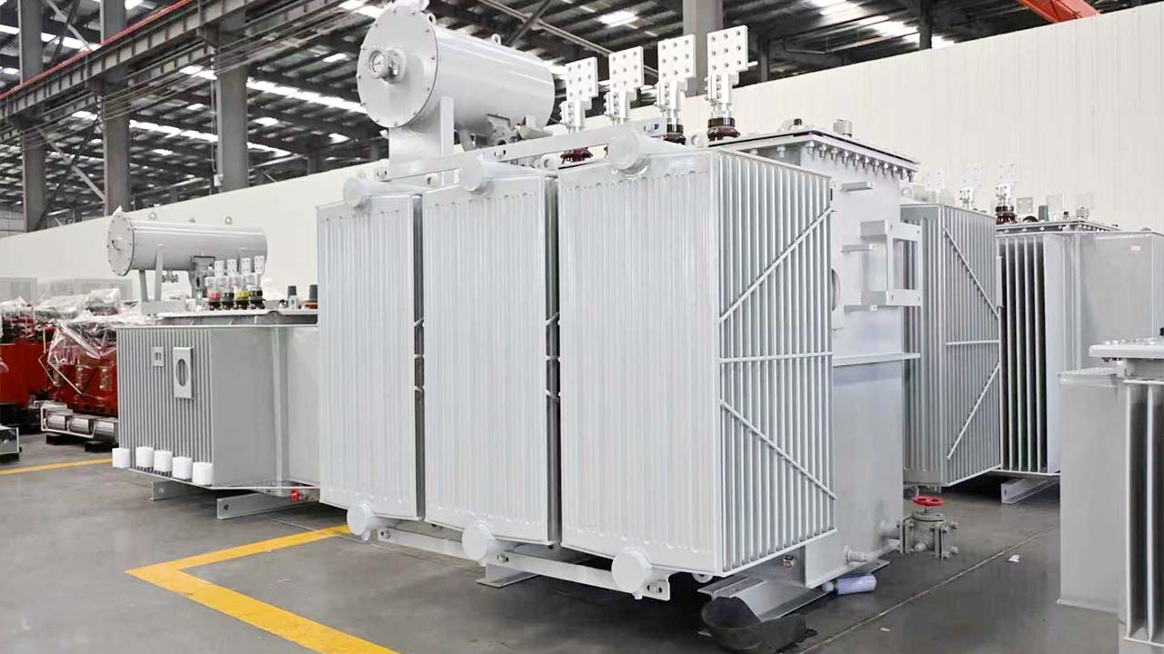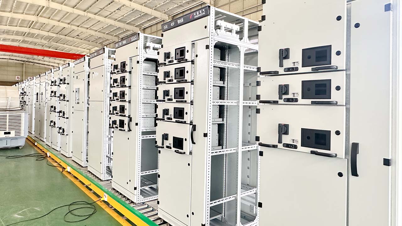
Electrical engineers, contractors, facility managers, and equipment buyers often need to convert transformer capacity from kVA to amps. This calculation is essential when selecting cables, circuit breakers, busbars, switchgear, protection devices, and downstream distribution equipment.
A transformer may be rated at 500 kVA, 1000 kVA, or 2500 kVA, but these values alone do not tell you the current flowing on the high-voltage or low-voltage side. The current depends on both transformer capacity and system voltage.
This guide explains the three-phase kVA-to-amps formula, provides practical calculation examples, compares current at different voltage levels, and introduces suitable ZHONGSHAO three-phase transformer solutions for industrial, commercial, renewable energy, and infrastructure projects.
Why Convert kVA to Amps?
Transformer capacity is expressed in kilovolt-amperes, while cables, breakers, busbars, and many protection devices are rated in amperes.
Converting kVA to amps helps engineers determine:
- Transformer full-load current
- Cable current-carrying capacity
- Circuit breaker rating
- Busbar size
- Switchgear current rating
- Fuse selection
- Protection coordination
- Power distribution capacity
For example, a 500 kVA transformer may produce more than 700 A at 400 V, but less than 30 A at 10 kV. The transformer capacity is the same, but the current changes significantly because of the voltage difference.
Three-Phase kVA to Amps Formula
The standard formula for calculating three-phase current is:
Current (A) = kVA × 1000 ÷ (√3 × Voltage)
Where:
- Current is the line current in amperes
- kVA is the transformer apparent power
- Voltage is the line-to-line voltage
- √3 is approximately 1.732
The formula can also be rearranged to calculate transformer capacity:
kVA = √3 × Voltage × Current ÷ 1000
For three-phase transformers, always use the line-to-line voltage, such as 400 V, 480 V, 10 kV, 13.8 kV, or 35 kV.
Why Is √3 Used?
A three-phase power system contains three alternating voltages separated by a phase angle of 120 degrees. Because of this phase relationship, three-phase apparent power cannot be calculated by simply multiplying voltage by current.
The √3 factor represents the mathematical relationship between line voltage, phase voltage, and total three-phase power.
For a single-phase transformer, the formula is simpler:
Current = kVA × 1000 ÷ Voltage
For a three-phase transformer, the √3 factor must be included.
Step-by-Step Calculation Example
Assume you have a 500 kVA three-phase transformer with:
- Primary voltage: 10 kV
- Secondary voltage: 400 V
High-Voltage Side Current
Current = 500 × 1000 ÷ (1.732 × 10,000)
Current = 28.9 A
Low-Voltage Side Current
Current = 500 × 1000 ÷ (1.732 × 400)
Current = 721.7 A
The same transformer carries approximately 28.9 A on the 10 kV side and 722 A on the 400 V side.
This example shows why high-voltage transmission reduces current and helps lower cable losses.
3-Phase kVA to Amps Quick Reference Table
The following table provides approximate full-load currents for common transformer capacities.
| Transformer capacity | Current at 400 V | Current at 480 V | Current at 10 kV | Current at 35 kV |
|---|---|---|---|---|
| 50 kVA | 72 A | 60 A | 2.9 A | 0.8 A |
| 100 kVA | 144 A | 120 A | 5.8 A | 1.6 A |
| 250 kVA | 361 A | 301 A | 14.4 A | 4.1 A |
| 500 kVA | 722 A | 601 A | 28.9 A | 8.2 A |
| 630 kVA | 909 A | 758 A | 36.4 A | 10.4 A |
| 1000 kVA | 1443 A | 1203 A | 57.7 A | 16.5 A |
| 1250 kVA | 1804 A | 1504 A | 72.2 A | 20.6 A |
| 2000 kVA | 2887 A | 2406 A | 115.5 A | 33.0 A |
| 2500 kVA | 3608 A | 3007 A | 144.3 A | 41.2 A |
These values are theoretical full-load currents. Final cable, breaker, and busbar selection must also consider installation method, ambient temperature, voltage drop, short-circuit level, applicable standards, and required safety margins.
How Voltage Affects Transformer Current
Current decreases as voltage increases.
Consider a 500 kVA transformer operating at different voltage levels:
| Voltage | Approximate current |
|---|---|
| 400 V | 722 A |
| 4.16 kV | 69.4 A |
| 13.8 kV | 20.9 A |
| 34.5 kV | 8.4 A |
This explains why medium-voltage and high-voltage systems can transmit large amounts of power using lower current.
Lower current can reduce:
- Cable cross-sectional area
- Conductor heating
- Voltage drop
- Line losses
- Busbar requirements
However, higher-voltage systems also require stronger insulation, suitable switchgear, greater electrical clearances, and more advanced protection.
Real Transformer Example: 3.15 MVA
Consider a three-phase transformer rated at:
- Capacity: 3.15 MVA, or 3150 kVA
- Primary voltage: 13.8 kV
- Secondary voltage: 480 V
Primary Current
Current = 3150 × 1000 ÷ (1.732 × 13,800)
Current = approximately 131.8 A
Secondary Current
Current = 3150 × 1000 ÷ (1.732 × 480)
Current = approximately 3789 A
Although the primary current is only around 132 A, the low-voltage side carries nearly 3800 A. This requires carefully designed low-voltage switchgear, busbars, cables, ventilation, and protection devices.
ZHONGSHAO Product Calculation Examples
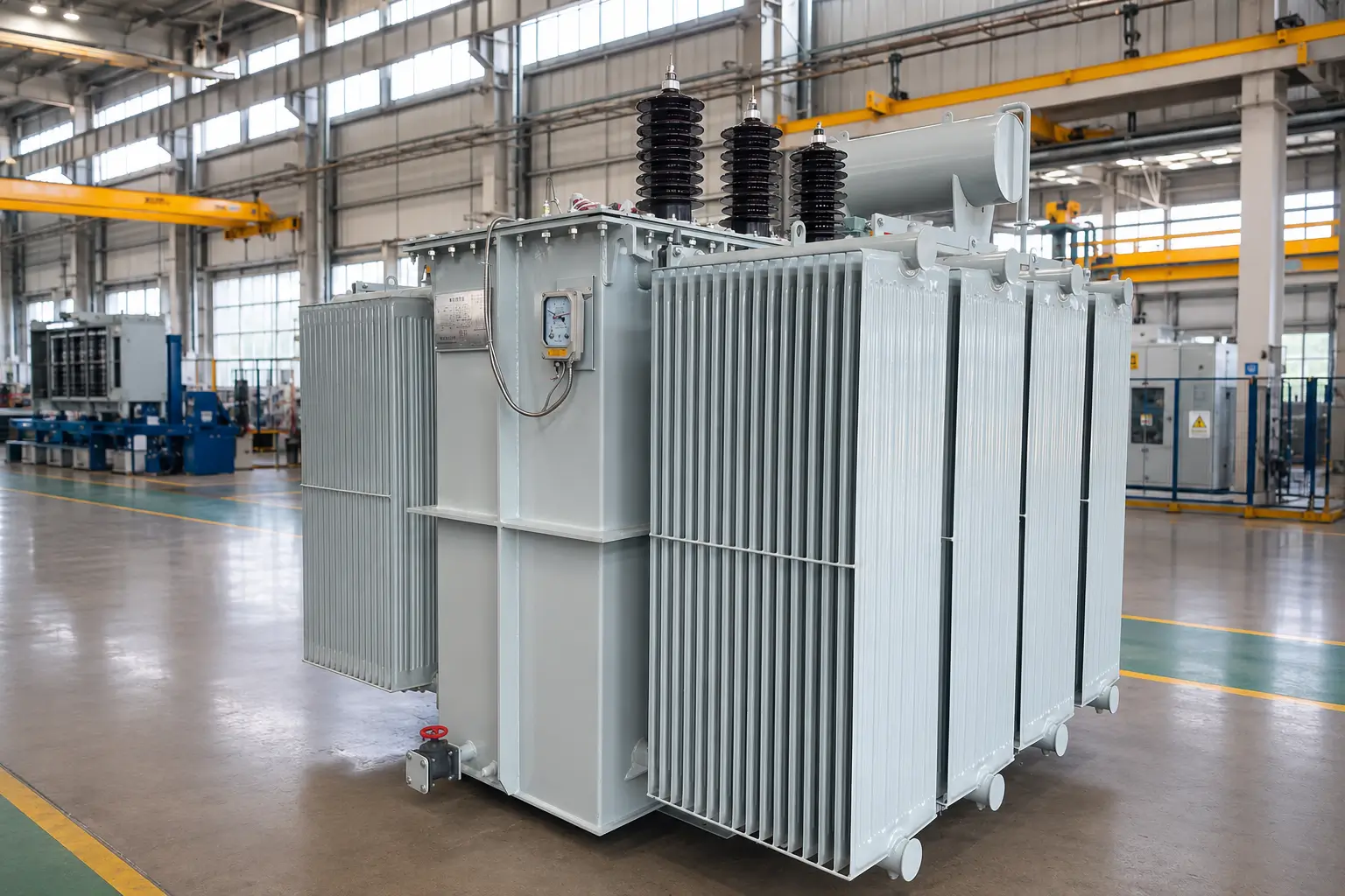
S13-M 500 kVA Oil-Immersed Transformer
Example specification:
- Model: S13-M-500/10
- Capacity: 500 kVA
- Primary voltage: 10 kV
- Secondary voltage: 400 V
Calculated currents:
| Transformer side | Full-load current |
|---|---|
| 10 kV side | 28.9 A |
| 400 V side | 721.7 A |
The S13-M fully sealed oil-immersed transformer is suitable for factories, outdoor substations, industrial parks, mining projects, and utility distribution systems.
Its oil-immersed design provides efficient cooling and reliable operation under continuous industrial loads.
The low-voltage switchgear must be selected according to the calculated full-load current, applicable safety factors, fault level, and local electrical code. In many projects, an 800 A or higher distribution system may be considered after engineering review.
SCB10 1000 kVA Dry-Type Transformer
Example specification:
- Model: SCB10-1000/10
- Capacity: 1000 kVA
- Primary voltage: 10 kV
- Secondary voltage: 400 V
Calculated currents:
| Transformer side | Full-load current |
|---|---|
| 10 kV side | 57.7 A |
| 400 V side | 1443 A |
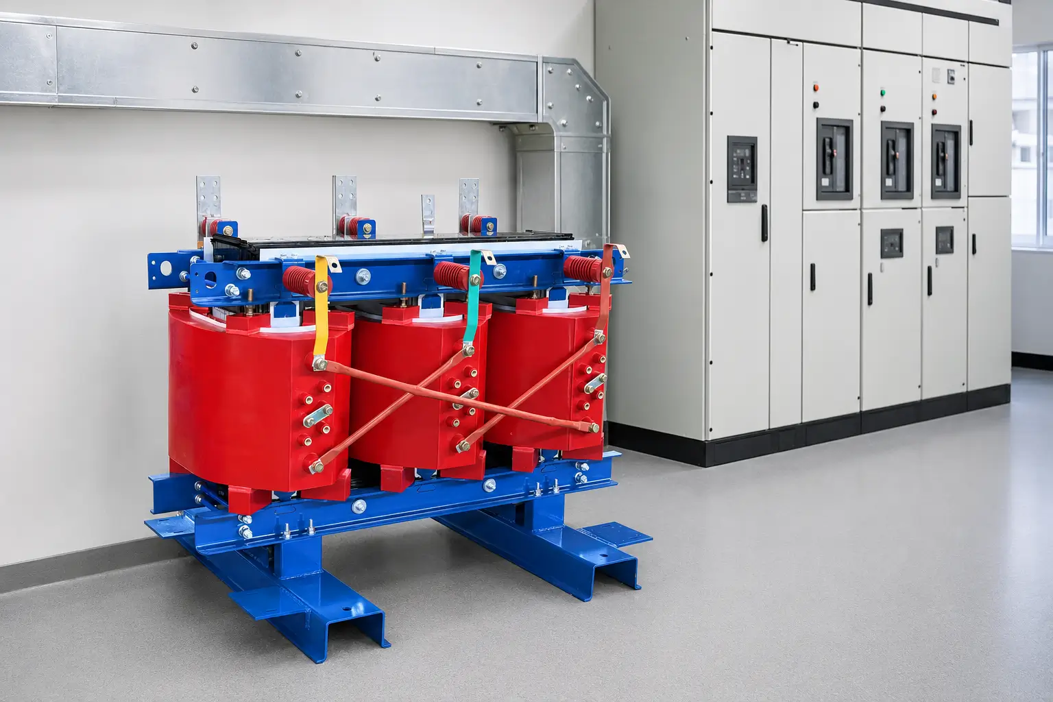
ZHONGSHAO’s SC(B) cast resin dry-type transformers are designed for indoor projects with strict fire-safety, environmental, and maintenance requirements.
Typical applications include:
- Data centers
- Hospitals
- Commercial buildings
- Food-processing plants
- Pharmaceutical facilities
- Indoor manufacturing plants
A 1000 kVA transformer with a 400 V secondary output requires substantial low-voltage current capacity. The connected switchboard, breaker, cable, and busbar system must be designed for the full-load current and expected short-circuit conditions.
ZGS11-12 1250 kVA Box Substation
Example specification:
- Model: ZGS11-Z-1250/12
- Capacity: 1250 kVA
- Primary voltage: 12 kV
- Secondary voltage: 480 V
Calculated currents:
| Transformer side | Full-load current |
|---|---|
| 12 kV side | 60.1 A |
| 480 V side | 1504 A |
The ZGS11-12 American-style box substation integrates the transformer, medium-voltage switching, low-voltage distribution, and protection devices in one compact enclosure.
It is suitable for:
- Solar power stations
- Wind energy projects
- Industrial parks
- EV charging facilities
- Remote mining sites
- Temporary construction power
- Fast-deployment infrastructure
ZHONGSHAO Three-Phase Transformer Options
ZHONGSHAO supplies several transformer types suitable for different current and voltage requirements.
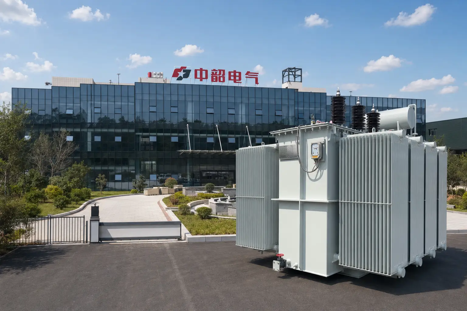
Three-Phase Oil-Immersed Transformers
Available options include 10 kV, 20 kV, and 35 kV transformer systems.
Typical benefits include:
- Strong cooling capability
- High overload performance
- Oxygen-free copper winding options
- High-quality CRGO core materials
- Reliable outdoor operation
- Compliance with applicable IEC and ANSI requirements
These transformers are suitable for factories, utilities, mining facilities, petrochemical projects, and renewable energy systems.
Three-Phase Dry-Type Transformers
SC(B) cast resin transformers provide an oil-free option for indoor applications.
Typical benefits include:
- Flame-retardant insulation
- Lower oil-related maintenance
- Environmentally safer operation
- Optional protective enclosures
- Good performance in commercial and industrial buildings
Three-Phase Pad-Mounted Transformers
Pad-mounted transformers can provide 208 V, 400 V, 480 V, and customized outputs depending on the project.
They are suitable for underground distribution networks, public areas, industrial facilities, renewable energy systems, and commercial developments.
Three-Phase Stabilized Transformers
For equipment sensitive to voltage fluctuation, ZHONGSHAO can provide customized three-phase transformer solutions with stable voltage output and protective functions.
These are suitable for precision manufacturing, automated production lines, testing equipment, and facilities requiring consistent voltage quality.
Practical Cable and Breaker Selection Tips
The calculated transformer current is only the first step.
Cable selection should also consider:
- Conductor material
- Insulation type
- Installation method
- Ambient temperature
- Cable grouping
- Permissible voltage drop
- Short-circuit withstand capacity
- Local electrical standards
Large low-voltage transformers may require multiple parallel cables or copper busbars.
Breaker selection must consider:
- Transformer full-load current
- Starting and energization current
- Short-circuit current
- Protection coordination
- Upstream and downstream device settings
- Applicable IEC, UL, NEC, or local requirements
A universal breaker multiplier should not be applied without reviewing the installation standard and transformer protection design. Final settings should be confirmed by a qualified electrical engineer.
Does Vector Group Affect the Current Formula?
No. The basic kVA-to-amps formula remains the same for common vector groups such as Dyn11, Yyn0, and Yzn11.
The vector group affects:
- Phase displacement
- Neutral availability
- Grounding arrangement
- Harmonic behavior
- Parallel-operation compatibility
It does not change the basic relationship between three-phase kVA, line voltage, and line current.
Common Calculation Mistakes
Avoid these common errors:
- Using line-to-neutral voltage instead of line-to-line voltage
- Forgetting the √3 factor
- Mixing volts and kilovolts without conversion
- Using kW instead of kVA without considering power factor
- Selecting cables only from theoretical current
- Ignoring ambient-temperature and installation derating
- Ignoring motor starting and harmonic loads
- Assuming the same current on both transformer sides
FAQ
Should I use line-to-line voltage?
Yes. For a three-phase transformer, use the line-to-line voltage in the formula.
Is the calculated current the actual operating current?
It is the theoretical full-load line current. Actual operating current depends on the connected load and operating conditions.
Why is low-voltage current so high?
For the same kVA capacity, lower voltage requires higher current. This is why large low-voltage transformers often require heavy busbars or multiple parallel cables.
Can ZHONGSHAO help verify the calculation?
Yes. ZHONGSHAO can review your transformer capacity, primary and secondary voltage, load type, single-line diagram, cable arrangement, and switchgear requirements.
Final Thoughts
The three-phase kVA-to-amps formula is:
Current = kVA × 1000 ÷ (1.732 × line-to-line voltage)
This calculation helps engineers select cables, breakers, switchgear, busbars, and protection devices. However, final equipment selection must also consider installation conditions, short-circuit levels, harmonics, motor starting, temperature, and applicable standards.
ZHONGSHAO supplies oil-immersed, dry-type, pad-mounted, stabilized, and power distribution transformers for industrial and infrastructure projects. With more than 100 electrical equipment patents and support for project requirements involving IEC, IEEE, ANSI, UL, CE, and ISO standards, ZHONGSHAO can provide customized three-phase power solutions.
Provide your required kVA, primary voltage, secondary voltage, frequency, installation environment, and single-line diagram to receive an accurate transformer and switchgear recommendation.