
Why Choose Our Three Phase Distribution Transformer?
- Manufacturing according to IEEE, ANSI, and IEC transformer standards
- Make sure equipment performance through turns ratio, insulation, and load testing
- Support multiple voltages and capacities to adapt to different power grids
- Support common wiring methods such as Dyn, Yyn, Dd, etc
- Widely used in substations, industrial and infrastructure projects
- Provide a complete three phase distribution transformer inspection report before leaving the factory
ZHONGSHAO - Your Trustworthy Manufacturer of Three Phase Distribution Transformer
As an electrical power equipment manufacturer with 15 years of experience, ZHONGSHAO specializes in the manufacturing and supply of three phase distribution transformers. We strictly manage every production process to make sure stable transformer quality and timely delivery.
We have over 50 R&D departments that can provide customized three-phase distribution transformers according to different needs, such as voltage levels, capacity configurations, and wiring methods.
Before leaving the factory, each transformer undergoes a comprehensive inspection including electrical performance, insulation condition, and operational status, etc. If you need three phase distribution transformers, please feel free to contact us.
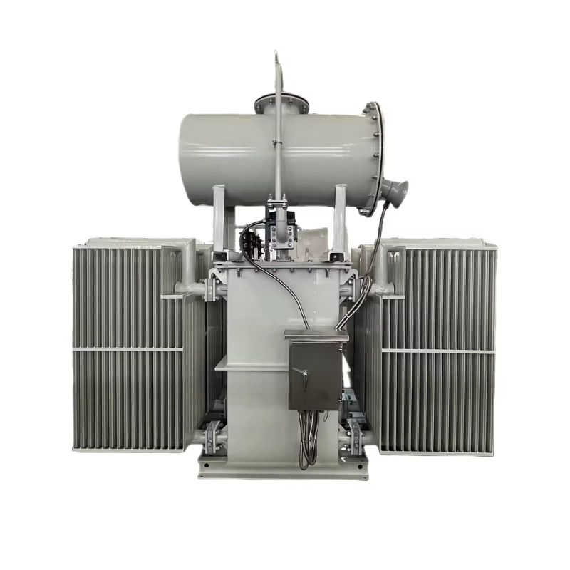
Using oil is used for cooling and insulation, and is widely used in industrial power systems and public distribution networks.
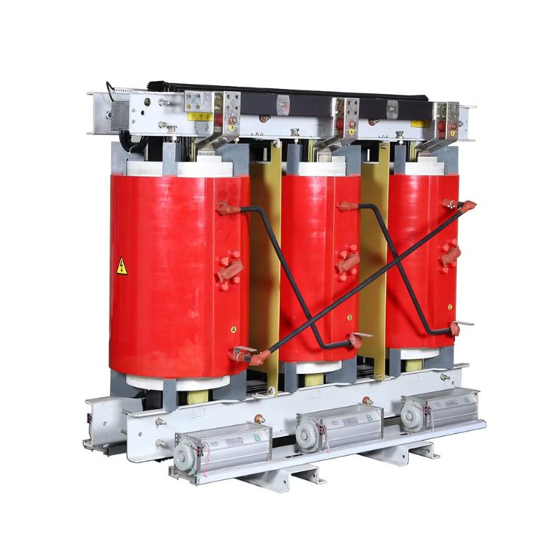
Adopting air cooling, it is suitable for buildings, commercial facilities, and places with high fire prevention requirements.
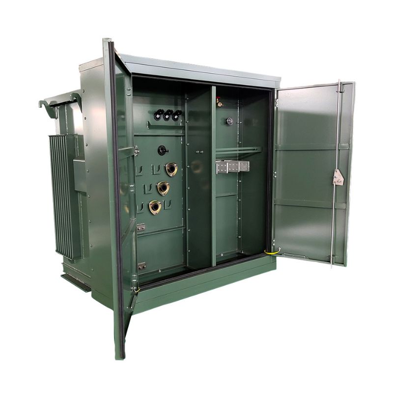
Installed in a sealed box, it is commonly used in urban underground power distribution systems and commercial areas for power supply.
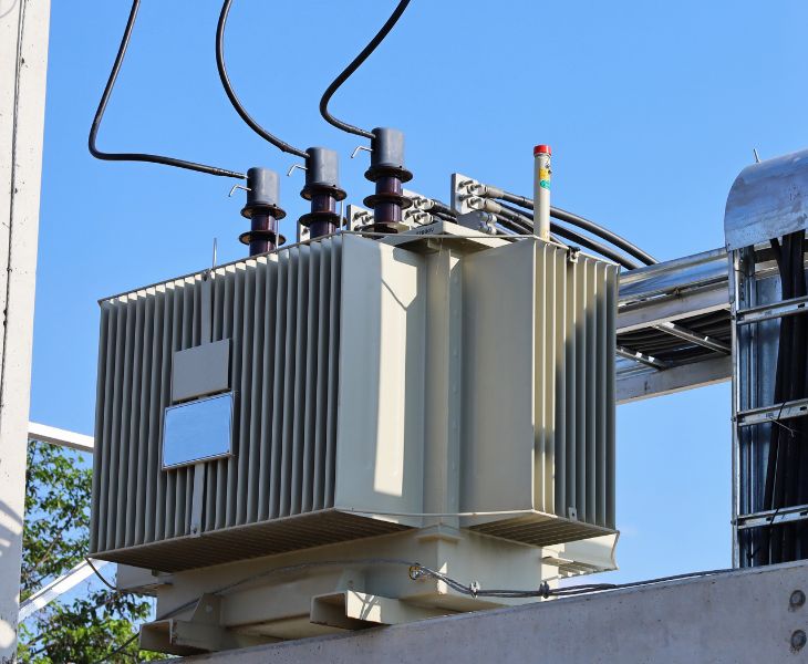
Installed on utility poles, it is commonly seen in rural power distribution lines and small industrial power supply systems.
Features of Three Phase Distribution Transformer

Adopting oriented silicon steel laminations to reduce eddy current and hysteresis losses, and improve electrical energy conversion efficiency.

High conductivity copper winding can maintain stable current transmission capability under different load conditions.

Adjust the transformer ratio through tap changer devices to adapt to voltage fluctuations and different load demands in the power grid.

Multilayer insulation materials isolate the winding from the iron core, improving electrical safety and reducing the risk of short circuits.
Manufactured Specifically for Distribution Network Applications
Our three phase distribution transformers are mainly used in industrial power systems, public distribution networks, and various infrastructure scenarios. During the design process, we will consider the electrical rated values, the winding connection methods, and the on-site installation conditions, so that the equipment can be integrated into the existing power distribution system. This way, you can quickly complete the installation without the need to modify the distribution network.
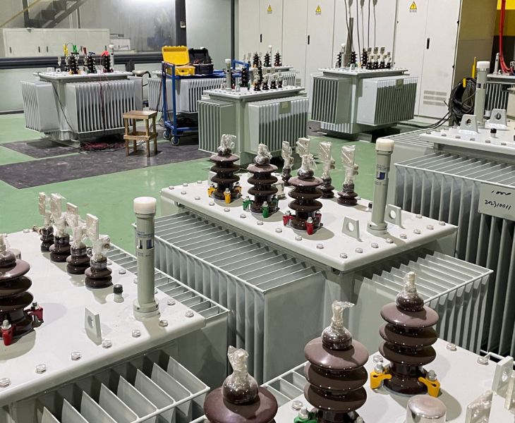
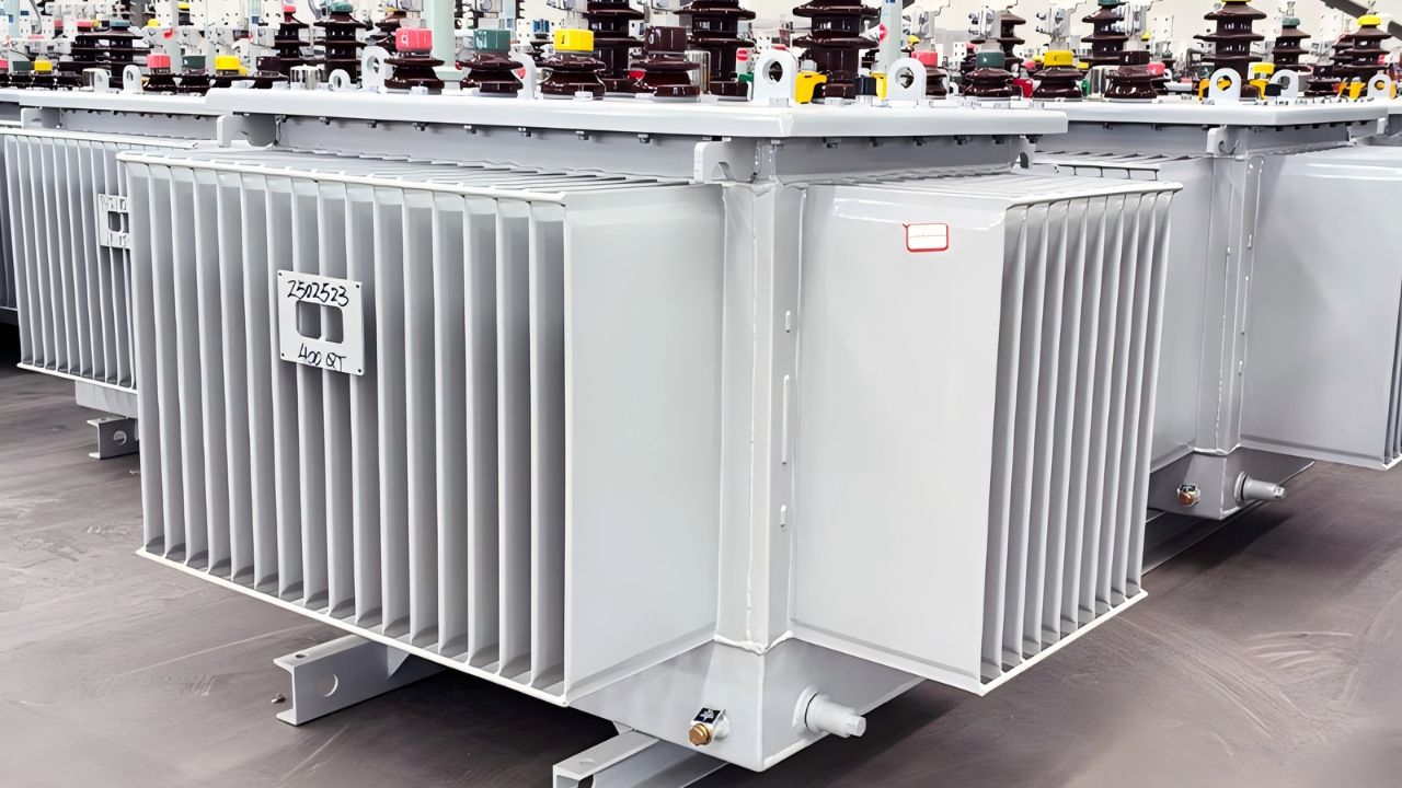
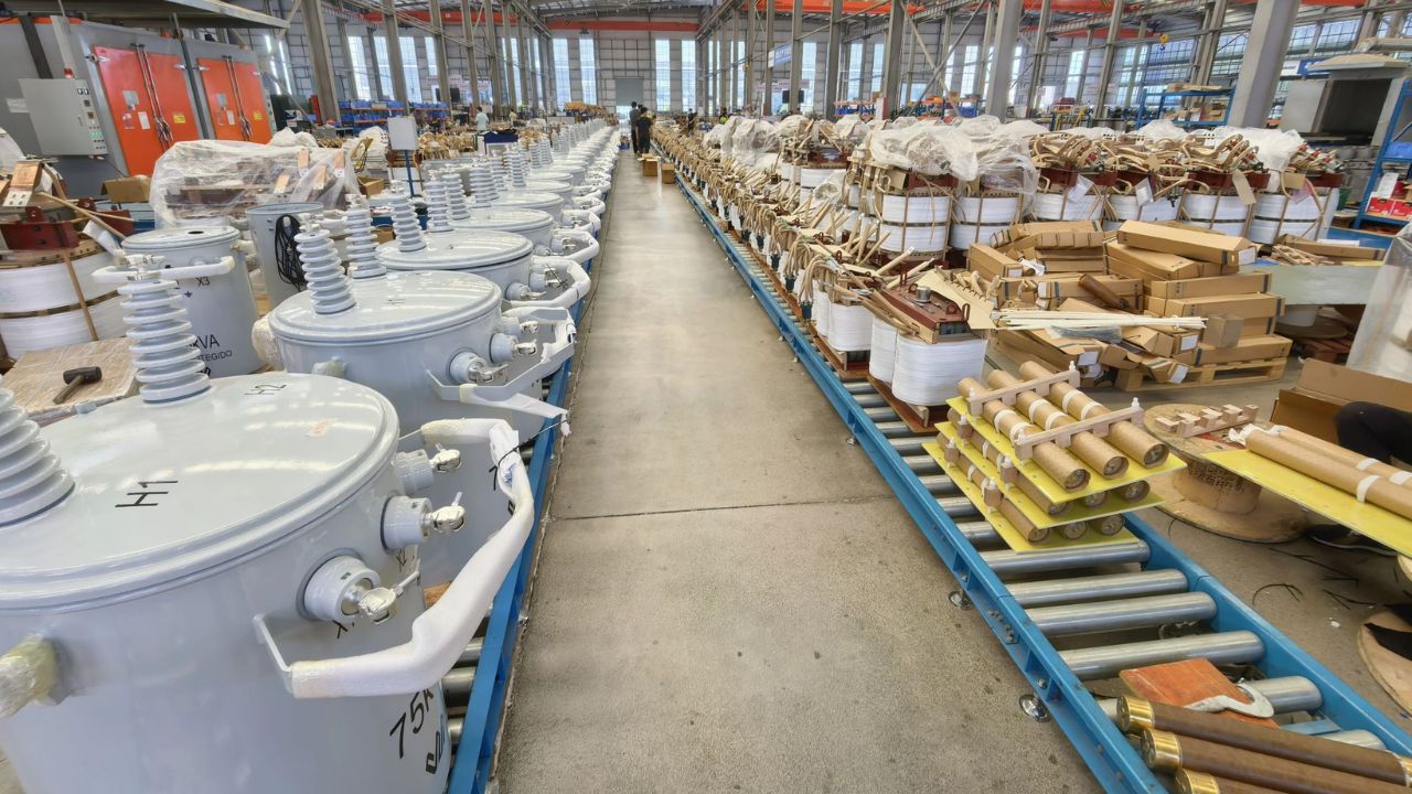
One-Stop Production
The entire process of transformer manufacturing includes iron core production, coil winding, insulation component processing, oil tank assembly, and final electrical performance testing. All these steps are completed within our own factory. Through one-stop manufacturing, each three phase distribution transformer can maintain consistent quality. At the same time, during the production process, we can also adjust the voltage level, capacity specification or wiring method according to your requirements to adapt to different power distribution systems.
Long term Stable Operation
Three phase distribution transformers usually need to operate continuously in industrial plants, substations and outdoor distribution networks, and withstand fluctuations in various electrical loads. We consider long term operational requirements and optimize the internal structure and insulation configuration of transformers to maintain stable performance under complex operating conditions. This can make the transformer reduce faults and maintain a stable power supply during long-term operation.
Applications of Three Phase Distribution Transformer

The three phase distribution transformer can provide stable power support for industries such as automotive assembly, steel smelting, chemical production, and food processing. For the impact loads of high-power motors, electric furnaces, and welding equipment, our transformers can maintain reliable operation to make sure the continuous operation of the production line. We have strengthened the insulation and protection capabilities of transformers to adapt to complex working conditions in the factory, such as dust, high temperature, and humidity.
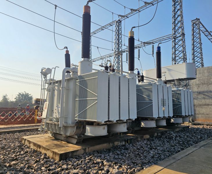
In urban and suburban distribution networks, three phase distribution transformers are required to convert medium voltage electrical energy into low voltage electrical energy and safely deliver the power to the user side. Whether installed in substations, community distribution rooms, or on poles, our transformers are compatible with the existing power grid and operate stably at different load rates. At the same time, our equipment has excellent outdoor protection capabilities and can still operate reliably in weather conditions such as rain, snow, high and low temperatures.

Our three phase distribution transformers can meet the internal power supply needs of large commercial complexes, hospitals, schools, airports, and other places. For the fire safety requirements of densely populated areas, our dry type three phase power distribution transformers are made of flame-retardant self-extinguishing materials and can be installed in indoor power distribution rooms. The transformer operates with low noise and can withstand mixed loads such as air conditioning, elevators, lighting and medical equipment.

In photovoltaic power stations and wind power plants, our three phase distribution transformers can adapt to the characteristics of new energy power generation. They can boost the low-voltage AC output by the inverter and then connect it to the medium-voltage collection line. For the intermittency and volatility of wind and photovoltaic power generation, our transformers have harmonic suppression and overload tolerance capabilities to make sure a reliable grid connection process.
The vector group of a three-phase distribution transformer is used to represent the connection method of the high voltage side and low voltage side windings, as well as the phase relationship between them. It is composed of letters and numbers, such as Dyn11 or Yy0. The letters represent the winding connection methods. D represents the delta connection, Y or y represents the star connection. The numbers represent the phase difference between the voltages on both sides and are indicated similarly to the positions of a clock.
When two transformers are operating in parallel, the phase relationship between their output voltages must be consistent. If the vector groups are different, there will be a phase difference between the voltages they output, resulting in circulating current. This circulation will increase the transformer’s power loss and cause the windings to overheat. In severe cases, it can damage the equipment. In addition, for transformers operating in parallel, they also need to meet conditions such as having the same transformation ratio, similar short-circuit impedance, and the same phase sequence.
The Dyn11 configuration employs a primary triangle connection and a secondary star connection, with a 30° phase difference. This specific vector group is widely applied in modern power grids. It can better reduce the third harmonic and handle unbalanced loads than the Yyn0 vector group. It allows the neutral wire to carry all rated currents and prevents neutral point displacement.
Star connection and delta connection are two common winding connection methods used in three-phase distribution transformers. The star connection connects one end of the three-phase winding to a common neutral point, thus allowing a neutral line to be drawn out of the system. The delta connection connects the ends of the winding to form a closed circuit.
The short-circuit impedance determines the current capacity that a transformer can withstand during a short-circuit fault, and it also affects the voltage regulation rate. The smaller the impedance value, the greater the short-circuit current, and the higher the requirements for the breaking capacity of downstream circuit breakers. But the voltage regulation rate is good, and the output voltage is more stable when the load fluctuates. The larger the impedance value, the smaller the short-circuit current, which is beneficial for protecting the equipment, but the voltage drop is greater when fully loaded.
What is the Three Phase Distribution Transformer?
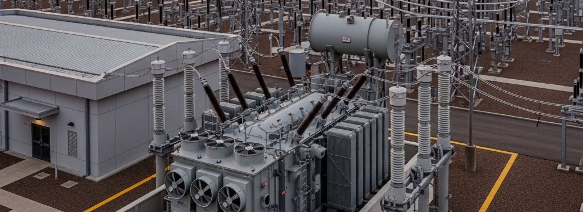
The three phase distribution transformer is an electrical device used in a three phase power distribution system. It is usually installed at the end of the distribution network. It can reduce the high AC voltage from the distribution grid to a low voltage suitable for direct use by industrial, commercial, and residential users.
The Composition of Three Phase Distribution Transformer
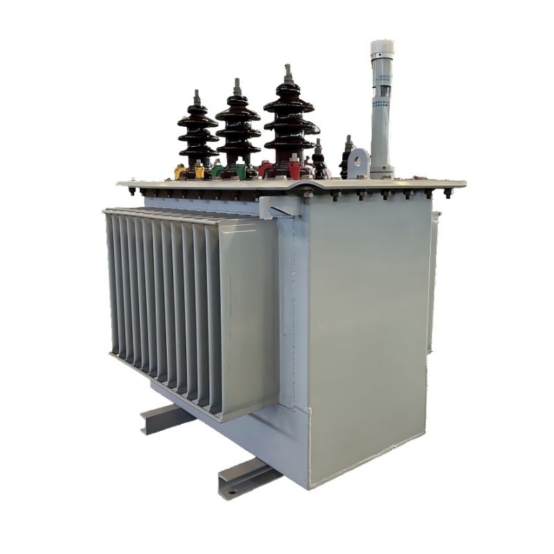
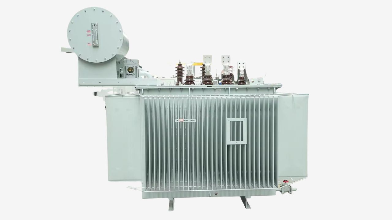 The three phase distribution transformer is mainly composed of the iron core, windings, insulation system, oil tank and accessories.
The iron core is usually made by stacking high permeability silicon steel sheets. The laminated structure can form a stable magnetic circuit while reducing eddy current losses and hysteresis losses.
There are three sets of primary and secondary windings arranged around the iron core. These windings are made of high conductivity copper or aluminum and separated by specialized insulation materials.
In oil immersed three-phase distribution transformers, the iron core and winding are placed in a reinforced steel oil tank. The fuel tank is filled with insulating oil, which has insulation and heat dissipation functions.
There are also high and low voltage insulation bushings in the transformer. The bushing is installed on the top of the oil tank, connecting the winding leads to the external circuit to make sure that the conductive parts are insulated from the oil tank.
In addition, there are some auxiliary components in the transformer, such as the tap changer used for adjusting the voltage, as well as safety devices like pressure relief valves and moisture absorbers.
The Working Principle of Three Phase Distribution Transformer
 The working principle of three phase distribution transformers is based on the law of electromagnetic induction.
When a three-phase AC voltage is applied to the primary winding, AC current flows in the winding and generates a time-varying magnetic flux in the transformer core. These magnetic fluxes form a magnetic circuit in the iron core and couple with both the primary and secondary windings at the same time.
As the magnetic flux keeps changing, it will induce an electromotive force in the secondary winding, thereby generating voltage on the secondary side and providing electrical energy to the external circuit.
The magnitude of the output voltage is determined by the ratio of the number of turns between the primary winding and the secondary winding. Therefore, by changing the ratio of the winding turns, it is possible to increase or decrease the voltage.
In a three phase distribution transformer, there are three sets of windings, corresponding to the three phase power supply. There is a phase difference of about 120° between the three phase voltages, resulting in three staggered magnetic fluxes in the iron core.
These magnetic fluxes work together to make the transformer transmit three phase electrical energy and form a stable and balanced three phase voltage output on the secondary side.
How to Select Three Phase Distribution Transformers?
Determine the Voltage Levels of the Primary and Secondary Sides
 You first need to confirm the input voltage level on the primary side and the output voltage level on the secondary side. The primary voltage must be completely consistent with the voltage of the connected power grid. The secondary voltage needs to meet the usage requirements of downstream electrical equipment or distribution systems.
The common primary voltage levels of three-phase distribution transformers include medium voltage levels such as 10kV, 20kV, and 33kV. The secondary side is usually at a low voltage of 400V or 415V, and is used to supply power to industrial equipment, lighting systems or power loads.
Calculate the Capacity of the Transformer
The capacity of a transformer is expressed in the unit of apparent power, kVA, to indicate the size of the output capacity of the transformer. You can use the three-phase power formula to calculate: required capacity kVA = (load voltage x maximum phase current x 1.732) /1000.
After completing the calculation, it is recommended to increase the margin by 15% -20% and then round it up to the standard specifications, such as 30kVA, 45kVA, 75kVA, 100kVA, etc. Long term operation of transformers near full load will accelerate the aging of the insulation system. An appropriate margin can help extend the service life of equipment.
Select the Winding Connection Method
 You need to select the winding connection method based on your load.
Dyn11 is the most commonly used vector group for three phase distribution transformers. The delta connection on the high-voltage side can provide a circulating path for the third harmonic, preventing the harmonic from flowing into the upstream power grid.
The low voltage side star connection method can lead out the neutral point and is suitable for carrying both three-phase and single-phase loads at the same time.
If your power supply is mainly for three-phase motor balanced loads, Yyn0 can also meet your basic needs.
Consider the Installation Environment
For outdoor installation, you can choose oil immersed three phase distribution transformers or dry type three phase distribution transformers with stainless steel casings. The protection level should be at least IP54, with the ability to resist rain, dust and ultraviolet rays.
For indoor installations such as crowded places like shopping malls and hospitals, we recommend choosing dry type three phase distribution transformers. It has flame-retardant and self extinguishing characteristics and low operating noise.
In high-humidity or dusty environments, a higher level of sealing and insulation is required to make sure long-term stable operation.
Low air density in high-altitude areas can lead to a decrease in heat dissipation capacity and a reduction in transformer capacity. For example, when operating at an altitude of 3000 meters, the available capacity of the transformer drops to about 94% of the rated value, and the insulation withstand voltage drops to 80%.
When choosing a transformer for a high-altitude project, you need to specify the actual installation altitude. We will make compensation during the transformer design phase to make sure that there is no overheating or insulation breakdown during operation.